


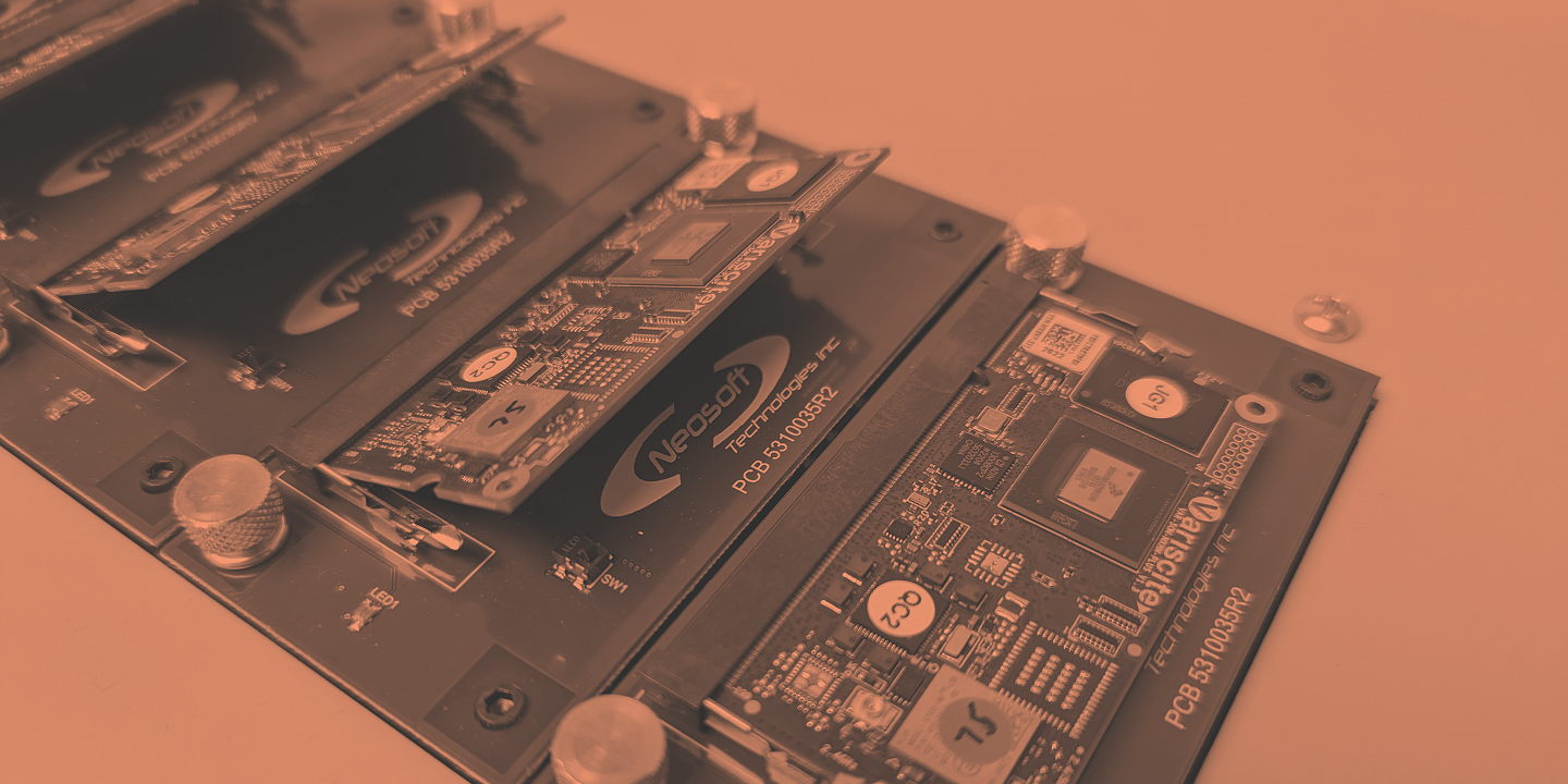
Automated and simultaneous flashing of SOMs
Neosoft developed an embedded SOM solution with automated LabVIEW deployment for fast and reliable industrial integration.
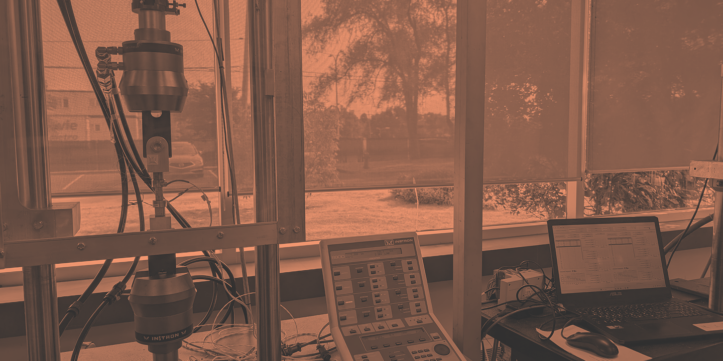
Automated charge cell calibration station
The calibration of load cells is essential to ensure the accuracy of force measurement systems used in test benches.
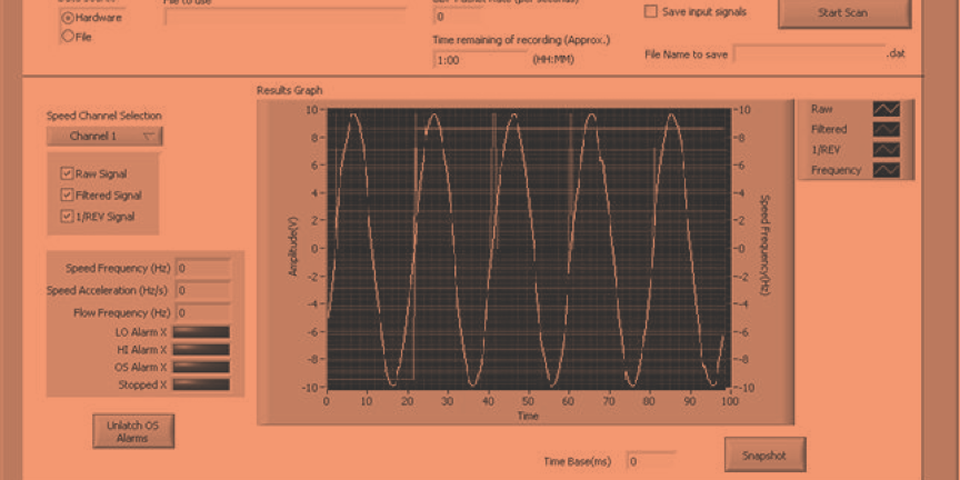
Frequency Processing System for Jet Engines
This project replaced an obsolete electronic board with a new frequency processing system for jet engines. Developed on an NI CompactRIO platform using LabVIEW Real-Time and FPGA, it ensures reliable signal acquisition, real-time analysis, and long-term system performance.