
Automated Fine Guidance Sensor alignment system
The goal was to automate the alignment of the Fine Guidance Sensor of a telescope. The final system aligned several telescopes mounted in an aluminum structure that is required to withstand space conditions (in a near vacuum and at -250°C). One of the goals for this system was to find the exact position of each telescope within a few micrometers. The aluminum structure distorts and shrinks when the temperature lowers, changing the telescope’s alignment. Our system is used to monitor all parameters, telescope alignment and optical characteristics of the light beam as the structure’s temperature increases from -250° C to +70° C. The structure, with telescope simulators, is shown in Figure 1.
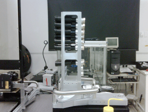
Figure 1 – Aluminum Structure with Telescope Simulators
The hardware system consists of two CCD cameras, one with a lens and the other without a len, mounted on a 3-axis moving stage system (XYZ). The three stages are moving in different directions in order to find the light beam generated by each telescope. To do so, images are taken periodically and analyzed to determine the position of the projected light beam and its optical characteristics. The NI Vision Development Module was use to perform image acquisition and processing, including a customized ‘centroid’ algorithm, used to find the centre of the light beam. The system must take measurements continuously to track the variations and several runs are done to insure extremely precise results (micrometer resolution). The position of each telescope was then saved on file for later analysis. Figure 2 represents a typical image of a telescope as seen by the CCD camera.
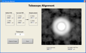
Figure 2 – Image of a telescope
This image was analyzed to determine several values, such as optical Point-Spread-Focal (PSF), Centroid, Intensity and Ellipsoid.
The software was built using LabVIEW 8.6, NI Vision Development Module and LabVIEW IMAQdx and runs on a laptop using Windows as the operating system. The three stages were controlled using a serial RS-232 command set. Figure 3 shows the user interface of the FGS Alignment System.
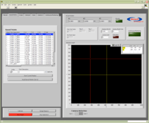
Figure 3 – User Interface of the FGS Alignment System